The Replica
Many of the points made in this section have been touched on in the first part. Here I’ll include greater detail. The lens is a 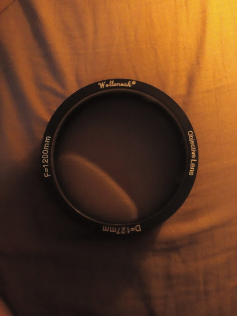 Wollensak 127mm 1200mm FL f/9.5 air spaced achromat. It is coated on the outer surface of each lens. It weighs in at nearly 5 pounds including the bezel. It was made by the Virginville optics company in Virginville Pa, also known at the Surplus Shed. The focus spot is ⅝” at 1200mm. The tube is made of clear pine boards, edge glued to make 12” on a side. 2 sides are cut to 10 ½” while the other two are cut to 12”. The boards were then measured and cut to the hollow pyramid shape, with 6” square on the lesser end (objective) and 12” square on the greater end. The sides were glued and screwed together with 1-2-3 block clamped inside to ensure right angles. Several joins were considered, including rabbet, mortised, and lapped. All these posed problems in either tooling or learning curve. With cost being an issue, the money to try and fail was simply not there, so simple but joints were used. Just before the midpoint of the tube there is an access hatch, it runs for 15” towards the large end. It is held in by machine s
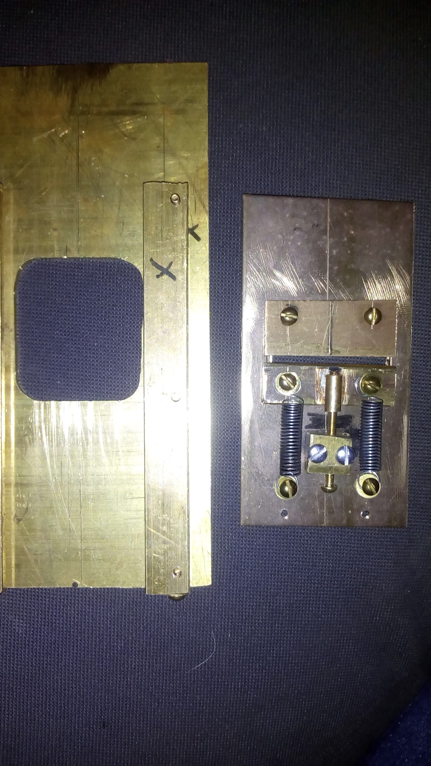 Photoheliograph final shutter assembly. Slit is not polished yet in this image. Credit: Chris Olsen.These are screwed into place with 4-40 screws. The slide is a 1/16” brass plate that is just shy of 2 ½” wide and 3 ½” long. This slides freely in the ⅛” gap provided by the slotted bars. Centered and moving down from the midline is a ¼”x1 ¼” slot. Above this slot are 2 threaded holes (4-40 used unless otherwise noted) that the upper, non adjustable slit edge screws into. Below this is a pillblock threaded 4-40, and posts for holding springs. The lower slot is a brass plate with a tube plugged in one end soldered onto it. The 4-40 jack screw slides readily in the tube and the opening and closing of the slit jaws are accommodated by screwing in or out the jack. Tension is kept even on the jaw by 2 small extending coil springs. On the bottom of the slide are 2 posts for attaching the rubber band that powers the shutter. On the upper end is a post that the trigger string is attached. There are holes on either side of the body tube that the jack screw and trigger string pass through.The shutter assembly is mounted on rails inside the body tube and can be
crews and threaded inserts. The lens is housed in an aluminum tophat which acts as a mount, sun shade, and angle adjustment. It is fastened to the body tube by 4 machine screws and threaded inserts. Between the mount and body there is a closed cell foam strip that allows for the lens angle to be adjusted by tightening or loosening the screws. Inside the tube is the shutter and the eyepiece/secondary lens. The shutter is truly the heart of the apparatus, as it allows the near instantaneous image to be flashed across the photographic plate. It consists of a ⅛” brass plate 3”x6” with a 1 1/2“ square opening in the middle. Along each long side is an L shaped brass slide. These were milled from a ¼ x ½” brass bar.
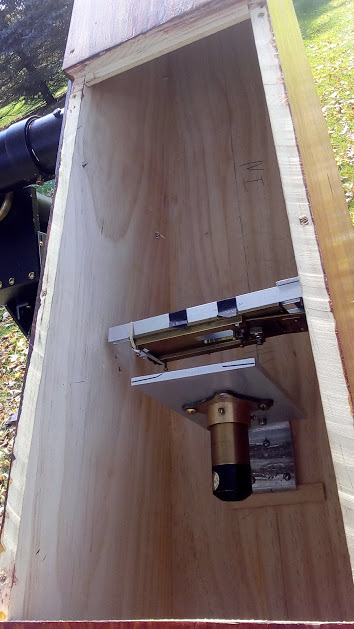 initial installation of the eye piece, just behind the shutter. a baffle would later be installed to keep all but the light coming from the aperture away from the photographic plate.adjusted for x-y axis and angle.
The lens is a Kellner style. The original used Huygens, however the required diameter Huygens could not be found. A Kellner is a single and a doublet lens, where a Huygens is 2 singles. There is a possibility that the lens will heat up and be ruined, however testing has not shown this to be a big concern. It is housed in a brass tube that slides within a bronze flange mount.
A good modification would be an radial focus mechanism. This mount is attached to the body tube on rails, and is adjustable on the x-y plane and angle. The materiel for these were sourced from plumbing fixtures, and machined to shape on a lathe.
The large end has the plate holder. It is a standard design, and is built up out of several pieces of wood to ensure uniformity. This is crucial so that the focus of each plate is the same from holder to holder. The holder attaches to the body via an oak box screwed onto the main body. It is held in by friction.
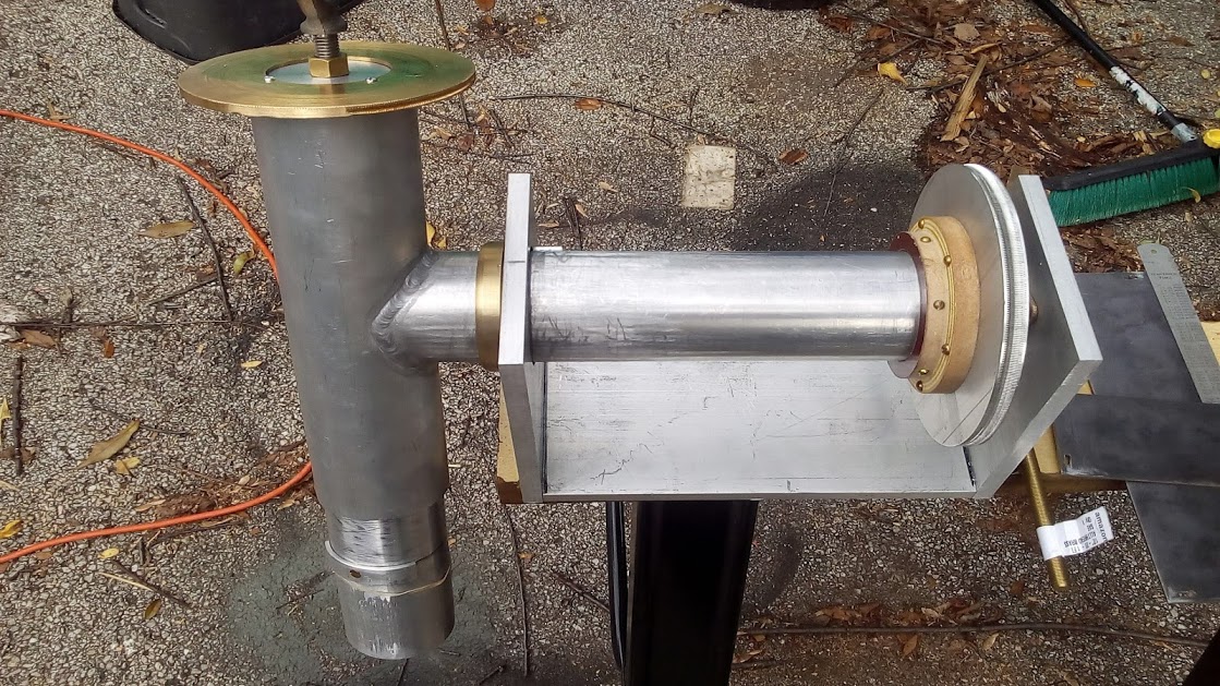
The GEM mount was fabricated from T-6 aluminum tube, and plate. The right ascension tube is 3” diameter, ⅛” wall tube. It is terminated on the lower end with a plug, which has been turned to fit into a bronze bearing. This tube passes through a brass bearing ring and then terminates with a 3 ½” ⅛” wall tube that has been welded perpendicular to the ascension tube. This tube is the bearing tube for the declination axis. The declination tube is the same material as the R.A. tube. The Dec. tube is terminated on either end with a solid bar of T-6. The lower end is ½” thick with a ½-13 tapped hole for the counterweight shaft. The upper ind is 3” long and is bolted in 6
 GEM mount in the white. The gear train was added to two plates on either side.
places to the tube. This plug is held onto the body tube mounting plate by 2 ¼-20 screws and one ½-13 screw. The mounting plate is held in 8 places to the body tube by #12 wood screws.
Attached to the R.A. shaft via a phenolic mounting bracket is the large drive gear. This is made of ½” aluminum, and is 7.62” (decimal is used here due to an uncommon fraction) diameter. It was hobbed out on a lathe using a ½-20 tap and a fabricated holder. The total number of teeth is 480. The rest of the clock drive is attached to ⅛” steel plates mounted onto either side of the R.A. shaft frame. It consists of 2 5:1 bronze gear sets, one idler gear and the 480:1 drive gear. The worm gear is brass ½-20 threaded rod with the ends turned down to match the other shafts. There are two methods of powering the drive. A shaft with a chain sprocket and weights with a friction clutch was the original, and first built method. This worked, however was not ideal for anything but reenacting. A small gear motor was employed with a battery and speed controller. The battery is a 6V 5 AH lead acid cell, and the speed controller is a PWM. This provides the motor with the 3.5V at .5 A it requires to turn the needed speed. All the gears are mounted externally to the unit for aesthetic reasons. There is a pinch hazard, however.
The mount ends were then trimmed to a rounded rather than squared off shape, and painted a ‘burnished bronze” black. Wedge pieces were fabricated to ensure a proper angle of ascension.
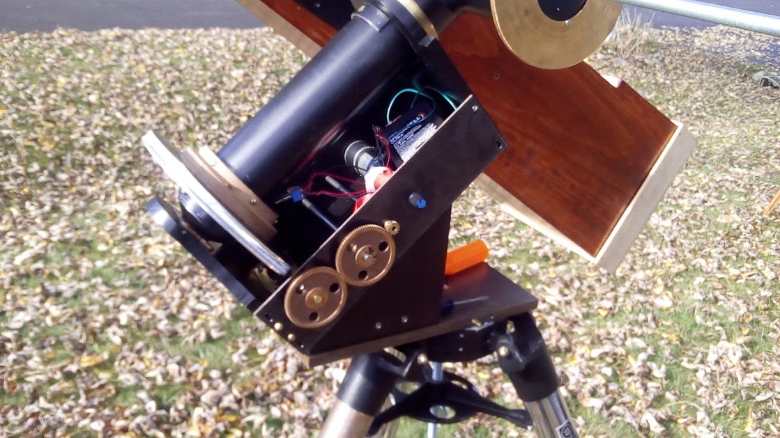 The operational configuration of the GEM mount. Shown is half of the drive train, the motor control and battery.
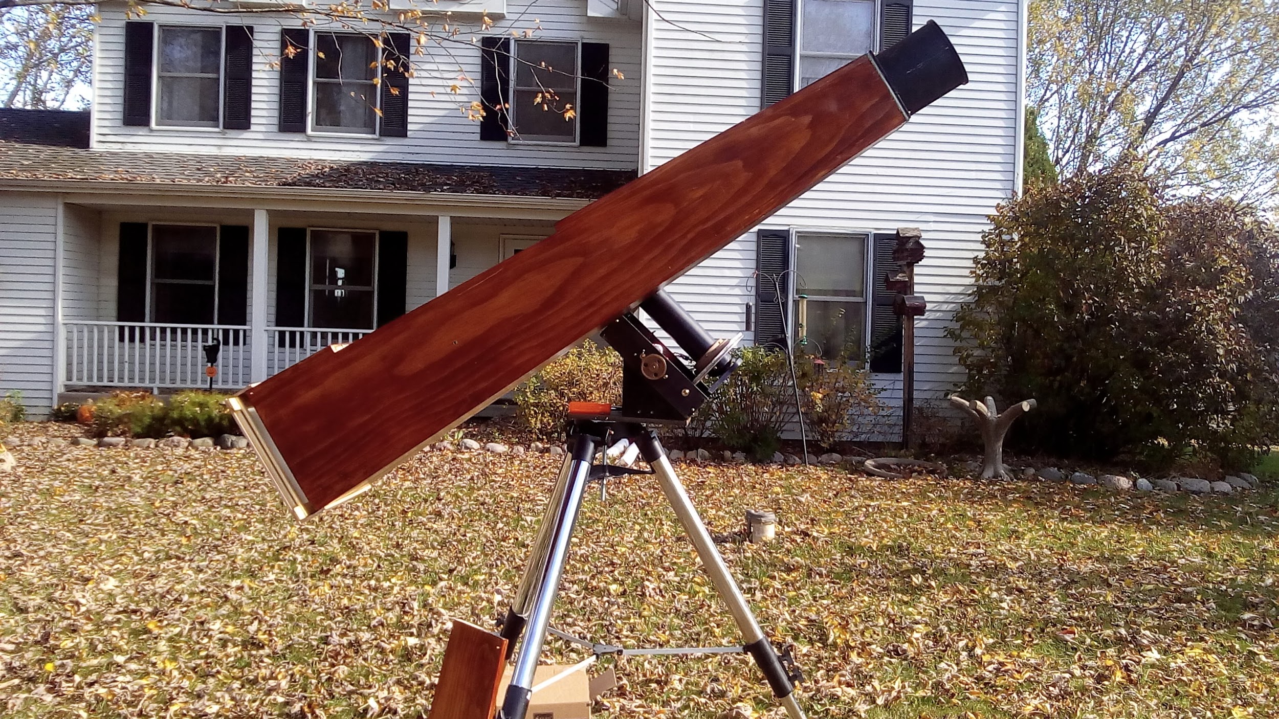 Final form of Photoheliograph on the drive – opposite the drive. Credit: Chris Olsen.